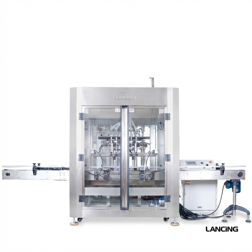
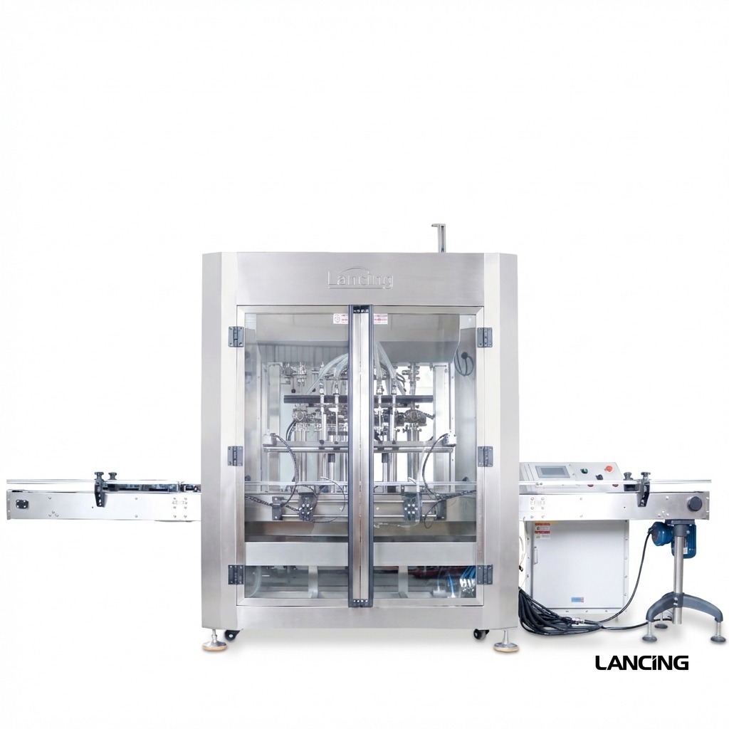
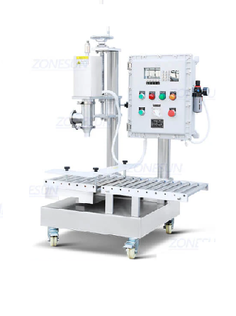
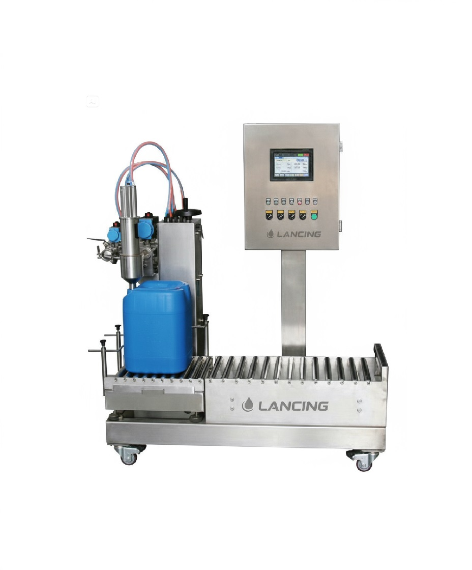
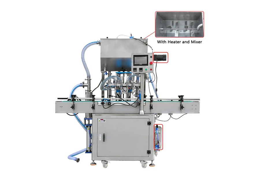
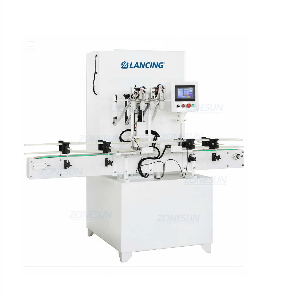
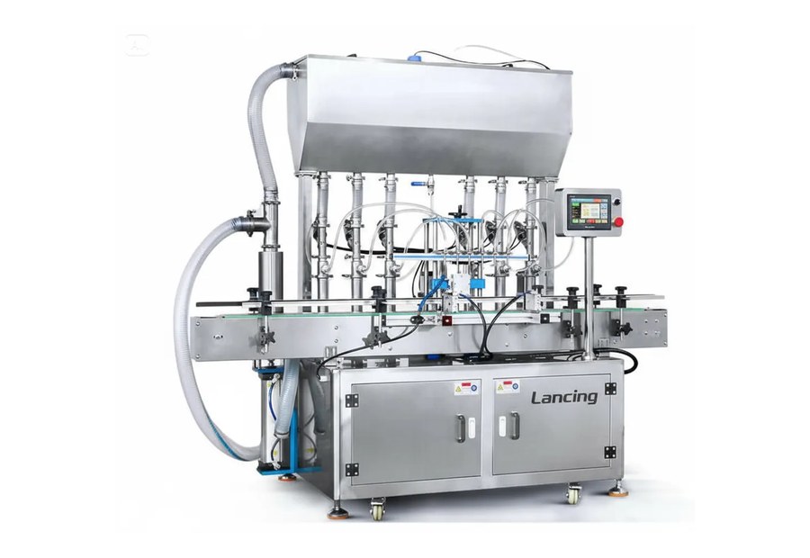
Automatic ATEX filling machine
For conveyor-fed production of compatible flammable liquids and solvents.
- 50–5000 ml reference route
- 1–6 heads
- Modular dosing options
Machine range
Compare automatic, weigh-based, semi-automatic and complete-line options, then narrow the choice around your product behaviour, container sizes and production target.

Compare machines
Use the options below to compare container sizes, dosing methods, product compatibility and automation levels.

For conveyor-fed production of compatible flammable liquids and solvents.

For 10–30 litre packs where mass-based filling is preferred.

Weighing, diving nozzles and heavy-container transfer for larger packs.

Integrated bottle feed, fill, cap, label and sorting modules.

Non-metal wetted-path options for aggressive liquids.

Positive-displacement filling for compatible viscous or stringing products.
Selection logic
Accuracy claims are only meaningful against the actual product, fill volume, speed and container presentation. Viscosity, foam, temperature, particles, product supply and nozzle cut-off can change the practical result.

Video demonstration
See the dosing, HMI and container movement on a working filling machine. Your final ATEX configuration is specified separately from the product data, hazardous-area classification, container and installation conditions.
Machine range FAQs
There is no single best principle. Piston, gear-pump, peristaltic, mass-flow, magnetic-flow and weigh filling can all be considered where compatible. Product behaviour, contact materials, required tolerance, cleaning and hazardous-area controls determine the shortlist.
Often yes, but the practical range depends on neck opening, container stability, fill volume, change-parts strategy, nozzle travel and changeover frequency.
No. Published values are reference platform figures. A project quotation should state the tested or expected performance for the declared product, dose, container and line conditions.
Your machine recommendation
Send your product SDS, container details, fill range, target output and any ATEX information. You’ll receive a practical shortlist matched to your application.
☎ 01494 623015✉ sales@lancinguk.comDirect support for new machines, line upgrades and complete filling projects.
Engineering comparison
The initial choice is normally controlled by product behaviour, the measurement method, the pack and the way vapour, drips and static are managed. A product trial can confirm fill behaviour, but the hazardous-area and equipment specification still requires competent classification information and an agreed conformity scope.
| Selection question | What to establish | Likely route to compare |
|---|---|---|
| How should quantity be measured? | Target volume or mass, tolerance method, density variation and legal/metrology requirements where applicable. | Piston, pump, flow-meter or load-cell weigh filling. |
| How does the product leave the nozzle? | Foam, splash, vapour, stringing, particles, drips and shut-off behaviour at the required rate. | Diving nozzles, positive shut-off, controlled fill profiles or a lower-speed trial. |
| How is the container presented? | Neck opening, stability, conductivity, filled weight, manual handling, indexing and changeover range. | Automatic bottle filling, operator-assisted stations or large-pack handling. |
| Where can an explosive atmosphere occur? | Release sources, zone boundaries, duration, ventilation, product transfer and downstream equipment affected. | Equipment and line scope developed from the competent site classification. |
| What must happen after filling? | Drip control, capping, labelling, coding, inspection, accumulation and discharge. | A stand-alone filler or a coordinated ATEX filling line. |
Hazardous-area context
HSE guidance describes gas, vapour and mist zones by the likelihood and duration of an explosive atmosphere. The room, the point of release and the inside of product-handling equipment can have different conditions. The competent classification should define the actual boundaries and the protection requirements used for machinery selection.
| Zone | HSE definition in practical terms | Information the machinery project still needs |
|---|---|---|
| Zone 0 | An explosive atmosphere is present continuously or for long periods. | Exact extent, gas or vapour group, temperature class, process enclosure, release control and the intended protection concept. |
| Zone 1 | An explosive atmosphere is likely to occur in normal operation occasionally. | Normal release scenarios, ventilation assumptions, operating procedures, equipment interfaces and access for inspection. |
| Zone 2 | An explosive atmosphere is not likely in normal operation and, if it occurs, will persist only briefly. | Abnormal release scenarios, boundaries, detection or ventilation measures and the equipment that remains inside the classified area. |
Share the current DSEAR assessment or hazardous-area drawing where available. When the assessment is incomplete, the machinery shortlist can remain provisional, but the final equipment category, marking, documentation and installation requirements cannot be closed on an assumption.
Further buyer questions
A preliminary discussion can begin with the SDS, process description and known site information. The final hazardous-area machinery specification requires competent classification inputs, so any quotation produced before they are available should clearly state the assumptions and outstanding responsibilities.
No. A trial can demonstrate filling behaviour, cut-off, foam control, container handling and cleaning under stated conditions. It does not replace the workplace risk assessment, hazardous-area classification, ignition-risk assessment or conformity process.
The operating modes, product changeover, cleaning, recipe control and area classification need to be reviewed together. A common machine may be possible, but every intended product and mode must be included in the agreed specification rather than treated as an informal future use.
Related Lancing specialists
This site remains focused on hazardous-area filling. For a general liquid-filler comparison without an ATEX requirement, use Liquid Fillers. For volumetric technology in its own right, use Volumetric Fillers. For broader packaging-line design outside the hazardous-area focus, use Packaging Lines. The ATEX project can link those technologies back to the site classification and ignition-control requirements.
Selection gates
Automatic, weigh and large-pack machines can overlap in nominal fill range. The better differentiators are the product behaviour, measurement method, container presentation and the way the line must operate inside or alongside the classified area.
Use the SDS, viscosity and density at operating temperature, conductivity where relevant, particles, foam, shear sensitivity and material compatibility to remove dosing methods that cannot handle the product or cleaning regime. This is more reliable than selecting a flammable-liquid filler from volume alone.
List minimum and maximum fills, every container and closure, product supply conditions, normal and abnormal stops, output target, changeover frequency and the site services available. The same solvent filling machine can behave differently when head pressure, temperature or downstream accumulation changes.
Plan samples and acceptance criteria around the expected constraint: nozzle cut-off, foam, load-cell stability, container movement, closure application, extraction permissives or cleaning. A trial should close a defined decision rather than provide an unstructured demonstration.
| Likely route | First question to answer | Evidence that normally matters next |
|---|---|---|
| Automatic ATEX filling | Can containers be presented and filled repeatedly at the required sustained output? | Product-feed stability, fill profile, nozzle cut-off, accumulation, capping and line controls. |
| ATEX weigh filling | Is mass the controlling quantity for the larger pack? | Tare method, scale stability, coarse/fine cut-off, drips and filled-pack movement. |
| Bucket, pail and small-drum filling | Can the heavier pack be located, filled, closed and removed safely? | Base and neck geometry, nozzle travel, ergonomics, conveyor isolation and closure handling. |
| Complete chemical filling line | Where does the classified boundary extend across the open-pack sequence? | Interface register, cause-and-effect logic, extraction, rejects, balanced output and SAT scope. |
Static control is not a universal accessory selection. Container material, transfer path and product behaviour need to be reviewed together; see the earthing, bonding and static-control guide. For non-hazardous general liquid-filling selection, use liquidfillers.co.uk rather than creating a competing route on this specialist site.
Expanded machine selection
Machine selection becomes clearer when the project separates three decisions: who moves the container, how the dose is controlled and what happens between the nozzle and a secure closure. The table below points to the detailed route for each decision.
| Primary decision | Routes to compare | Project evidence |
|---|---|---|
| Automation | Semi-automatic or automatic ATEX filling. | Campaign length, staffing, operator task, sustained output and downstream stages. |
| Measured quantity | Load-cell / weigh filling or piston, pump and suitable flow-based routes. | Mass or volume target, density, temperature, tare, tolerance and test method. |
| Container format | Bottles, jerrycans, pails or drums and large packs. | Dimensions, weight, neck/opening, stability, material, closure and handling. |
| Line boundary | Stand-alone filler or complete fill-cap-label line. | Infeed, open-container route, capper, coding, inspection, labelling, rejects and discharge. |
| Site integration | Installation, extraction and interlocks. | Classification, layout, utilities, interface owners, FAT and SAT evidence. |
Machine selection questions
The best machine family follows the operating case. These questions help buyers compare automation, measurement and project scope without treating a catalogue label as a final specification.
An operator-assisted or semi-automatic route is often the first option to investigate when batches are small, formats change frequently and continuous conveyor output is not the main objective. That does not reduce the need for appropriate hazardous-area equipment, permissives, earthing or bonding, extraction interfaces and controlled operating procedures.
Compare the complete operator task: presenting and confirming the pack, making any monitored connection, starting the cycle, dealing with drips, fitting the closure and moving the filled container. A flexible station is only useful when those actions are safe, repeatable and ergonomically practical.
Load-cell filling deserves priority when the required acceptance quantity is mass, container sizes are larger, product density can vary, or the buyer wants a direct recorded weight rather than an inferred volume. The decision still depends on tare variation, required net or gross result, platform stability, product flow, nozzle cut-off and the time needed for the reading to settle.
Volumetric or timed methods may remain practical for other duties. The load-cell versus volumetric comparison explains how to define a reproducible test instead of assuming one method is universally more accurate.
Compare quotations against one scope matrix that separates machine supply, site works, interfaces, documents, tests and exclusions. Two proposals may both describe an ATEX filler while one includes container handling, extraction interlocks, capping controls and installed testing and the other stops at the dosing station.
List the declared hazardous-area information, products and packs, dosing basis, output test, product supply, utilities, extraction, earthing or bonding, guarding, downstream interfaces, FAT, SAT, documentation and training. Differences then become engineering decisions rather than hidden commercial assumptions.
A filler feature is supplied and verified as part of the machine; a site interface is a condition or service the machine relies on but that another party provides or approves. Product valves, nozzles, machine sensors and control logic may sit within the machine scope. Area classification, room ventilation, building extraction, product feed, drains, fire strategy and final installation verification may be shared or site-owned.
Every interface should have an owner, technical requirement, signal or connection definition and acceptance method. The ATEX upgrade question guide shows why these boundaries matter when equipment is retained.
See the ATEX filling machine questions hub for focused answers on zone selection, plastic containers, line output, retrofit and nozzle choice, then use the existing machine pages to compare practical routes.

Compare proposals consistently
A buyer cannot compare two machines fairly when one quotation includes the product supply, extraction, static controls, capping and acceptance evidence while another lists only the filler. Convert the operating case into an evidence matrix before comparing price, output or lead time.
| Comparison area | Question for each supplier | Evidence to retain |
|---|---|---|
| Product and wetted path | Which formulations, temperatures, cleaning chemicals and product-contact components are inside the proposed scope? | SDS revision, product schedule, material list, supplier recommendations and trial limits. |
| Hazardous-area duty | Which approved zone and operating assumptions have been used, and what remains for the site to confirm? | Classification drawing, marking schedule, instructions and interface register. |
| Sustained production | Which complete cycle, pack range, rejects, stops and changeovers support the stated output? | Cycle basis, representative test plan and accepted-pack calculation. |
| Fill-to-close process | How are open filled packs transferred, capped, inspected and controlled during a fault? | Line layout, cause-and-effect schedule and closure acceptance method. |
| FAT and SAT | What will be proven at the supplier, what needs the final site and who closes each action? | Traceable FAT protocol, SAT list, deviations and signed acceptance records. |
The existing video demonstrates a working Lancing servo filling sequence, HMI and container movement; it does not prove the final ATEX configuration for another product or site. Use it as first-party process evidence, then define the product trial, marking, controls and installation separately.
Compare the intended machine duty and limits against the same approved area information. Do not score a quotation by the number of Ex-marked components without checking the assembled equipment, mechanical ignition sources and site interfaces.
Include capping when the open filled container, closure feed, transfer or downstream stop materially affects vapour, handling or sustained output. The complete line can then be assessed as one operating sequence.
Send the same product, pack, site and output evidence to each supplier. Use the ATEX specification checklist and state which items are confirmed, provisional or still awaiting competent review.
Classification-led selection
The Zone, gas group, temperature class, equipment duty, product behaviour and control dependencies need to be understood together. Use the new gas-group and temperature-class guide, the LEL detection and ventilation-interlock guide and the answer explaining ATEX versus DSEAR before the machine architecture is frozen.
Share the approved Zone drawing, gas or vapour group, temperature requirement, extent and any external measures relied on by the equipment.
Define whether movement and control are pneumatic, electro-pneumatic or electric without assuming one architecture is universally safer.
List extraction, gas detection, product isolation, capping, conveyors and building systems that affect the safe state.
Additional machine-selection routes
Large packs
Review palletised containers, weighing or metering, nozzle access, extraction, earthing and overfill protection.
Open the large-pack guide →Measurement
Compare what each method measures and the product, pack and acceptance variables that decide suitability.
Compare the methods →Zone selection
Understand the protection level and evidence needed for equipment actually located in Zone 0.
Read the answer →Compare equivalent evidence
A quoted filler tolerance only becomes comparable when both proposals use the same product, target quantity, container, tare convention and verification method. Specify how a restart, changeover or batch-end condition is represented. Do not equate display resolution with fill accuracy or compare a closed-pack net weight with a freshly filled open container without recording the difference.
Use the accuracy and checkweighing guide to define the test. For formulations that need additional controls, review solvent-based ink packaging or separate resin and hardener packing. These application reviews supplement the existing machine families; they do not extend any published model specification.
Send one common test brief with your enquiry so the shortlisted routes can be compared on the same basis.
Share your SDS, hazardous-area information, containers, fill volumes, target output and any capping or labelling stages.